
An industrial cellular modem looks like the simplest device in a remote monitoring system. It takes data from a serial port and carries it over the mobile network. Yet a large share of commissioning problems at remote sites come from exactly this link: a parity setting that does not match, frames that arrive split in two, a master that gives up waiting before the reply arrives, or a server that the modem cannot reach.
This guide walks through the configuration of a serial-to-cellular modem in six parts, from wiring to verification, using Modbus RTU as the main example because it is the most common protocol on such links. It closes with a troubleshooting table and the E-Lins modem options.
Part A: Get the Wiring Right
RS232
RS232 is point-to-point and intended for short distances, typically around 15 metres. The transmit line of one side must reach the receive line of the other. If the modem and the device are both wired as the same equipment type, a crossover (null-modem) cable or adapter is needed. Check whether the device expects hardware flow control; most industrial devices do not.
RS485
RS485 is a differential bus, normally used in two-wire half-duplex form for Modbus. It supports multiple devices on one pair over long distances, up to roughly 1,200 metres at lower baud rates. Terminate the two ends of the bus with 120-ohm resistors, keep stubs short, and use twisted-pair cable with a common reference conductor. Manufacturers do not label the two lines consistently: if nothing communicates, swapping A and B is a quick first test.
Part B: Match the Serial Parameters
The modem's serial port must match the device exactly: baud rate, data bits, parity, and stop bits. The Modbus serial line specification sets even parity as the default and calls for two stop bits when no parity is used, but many devices in the field are configured as 8 data bits, no parity, one stop bit. What matters is not which setting is "correct" but that both ends agree. Read the setting from the device itself rather than from its manual, since installers often change defaults.
Part C: Understand Framing
Modbus RTU marks the end of a frame with silence. The specification requires a gap of at least 3.5 character times between frames. At 9,600 baud, with 11 bits per character, one character takes about 1.15 milliseconds, so the gap is about 4 milliseconds. Above 19,200 baud, the specification recommends a fixed gap of 1.75 milliseconds.
A modem that forwards serial data over the network has to decide when a frame is complete before sending it. Most do this with a configurable idle time or packing interval, sometimes combined with a maximum packet length. If the interval is shorter than the pauses some devices leave inside a frame, frames are split across packets, and the master rejects them. If it is much longer than needed, every reply is delayed. Start with a value a little above the frame gap for the baud rate in use, then adjust while watching real traffic.
Part D: Choose the Network Mode
TCP client
The modem opens a connection to a server address and port. This is the most common mode on cellular networks, because operators often place devices behind carrier-grade NAT, which blocks unsolicited inbound connections. The server, often a SCADA front end or a serial-over-IP driver, must listen on a fixed, reachable address.
TCP server
The modem listens, and the master connects to it. This only works if the modem is reachable, for example through a private APN with fixed addresses or a VPN.
UDP
UDP has less overhead and suits some polling systems, but provides no delivery guarantee; the master's retries must handle lost packets.
RTU over TCP versus Modbus TCP
In transparent mode, the modem carries the original Modbus RTU frames inside a TCP or UDP stream. The master must therefore use an "RTU over TCP" or encapsulated mode. Modbus TCP proper, usually on port 502, uses a different header without the RTU checksum, so a master set to Modbus TCP will not understand transparent RTU traffic unless a gateway converts between them.
Keepalives
Carrier NAT tables and idle timers close quiet connections. Configure heartbeat or keepalive messages at an interval shorter than the network's idle timeout, but not so short that they waste data.
Part E: Tune the Master
A serial master on a local line may expect a reply within a few hundred milliseconds. Over cellular, round trips are longer and vary, and the first message after a quiet period can take noticeably longer while the radio reconnects. Set response timeouts in seconds rather than milliseconds, allow at least one retry, and avoid polling many devices on the same bus in parallel through one modem. If polling cycles become too long, reduce the number of registers read per cycle or move to report-by-exception where the protocol supports it.
Part F: Verify Before Leaving Site
|
Check |
How |
Expected result |
|
Serial link |
Local poll from a laptop on the device's port |
Device answers locally |
|
Registration |
Modem status page or management platform |
Attached to the network with usable signal |
|
Server connection |
Server log or modem status |
Connection established and stable |
|
End-to-end poll |
Poll from the SCADA master |
Correct values, no CRC errors |
|
Recovery |
Power-cycle the modem |
Reconnects without intervention |
|
Signal record |
Note signal level and quality |
Baseline for later troubleshooting |
Troubleshooting Common Faults
No reply at all: check A/B polarity, termination, and serial parameters, then the server address and port.
CRC errors or partial frames: adjust the packing interval and check that the master is in RTU over TCP mode.
Replies arrive after the master has given up: lengthen the master's timeout and add a retry.
Link drops after a quiet period: add or shorten keepalives.
Works for hours, then fails: check power stability and whether the device recovers automatically.
E-Lins Industrial Cellular Modems
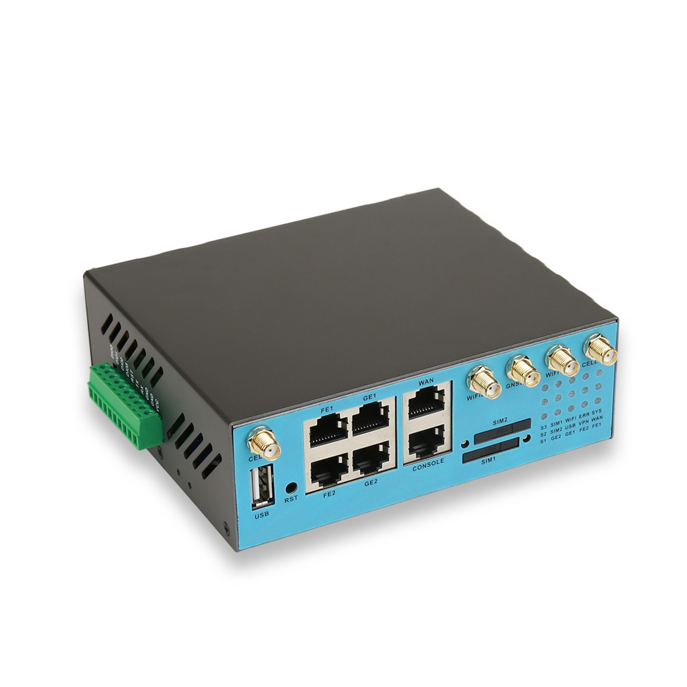
E-Lins builds industrial cellular modems specifically for this job. The M300 and M400 4G modems provide RS232 and RS485 to 4G transparent transmission, and the M300t accepts a wide-voltage DC input for cabinets with unstable supplies. For sites moving to 5G, the H685f IoT 5G modem combines 5G SA/NSA with two Gigabit Ethernet ports, an RS232/RS485 serial port, four digital inputs and outputs, and GPS/BeiDou. The H685f-G 5G GPS modem adds DIN-rail mounting with an RS232 port, and the H900pfrc RedCap modem offers dual SIM with 4G failover. Across the 5G modem range, E-Lins lists Modbus and DNP3 among supported industrial protocols, with MQTT for cloud platforms, and management through the web interface, SSH, TR-069, SNMP, and the E-Lins NMS cloud platform.
The same serial-to-network principle underlies E-Lins solution designs such as a natural gas pipeline in Thailand, where remote terminal units at compressor stations report to a SCADA centre over serial links carried by cellular equipment.
Support and the Manufacturer
E-Lins provides configuration manuals, video tutorials and one-to-one remote guidance, together with 7x24 remote technical support that includes packet capture analysis and remote debugging, which is often the fastest way to see whether a framing or timeout problem lies in the modem, the network or the master. Shenzhen E-Lins Technology Co., Ltd. began in the industrial sector in 1999 with modems for power grids and oil fields, and today supplies industrial cellular modems and routers to customers in more than 150 countries and regions. Configure the six parts carefully, and the industrial cellular modem becomes the quiet, dependable link it is meant to be.
https://e-lins.com/
Shenzhen E-Lins Technology Co., Ltd.





+ There are no comments
Add yours