
The GF402 tube cutting head is a component worth evaluating when optimizing the performance of an industrial laser tube cutting system. In high-volume manufacturing, cutting efficiency is not determined by laser power or programmed speed alone. Actual productivity depends on stable beam delivery, reliable piercing, effective assist-gas control, consistent tube positioning, and the ability to maintain process quality throughout extended production runs.
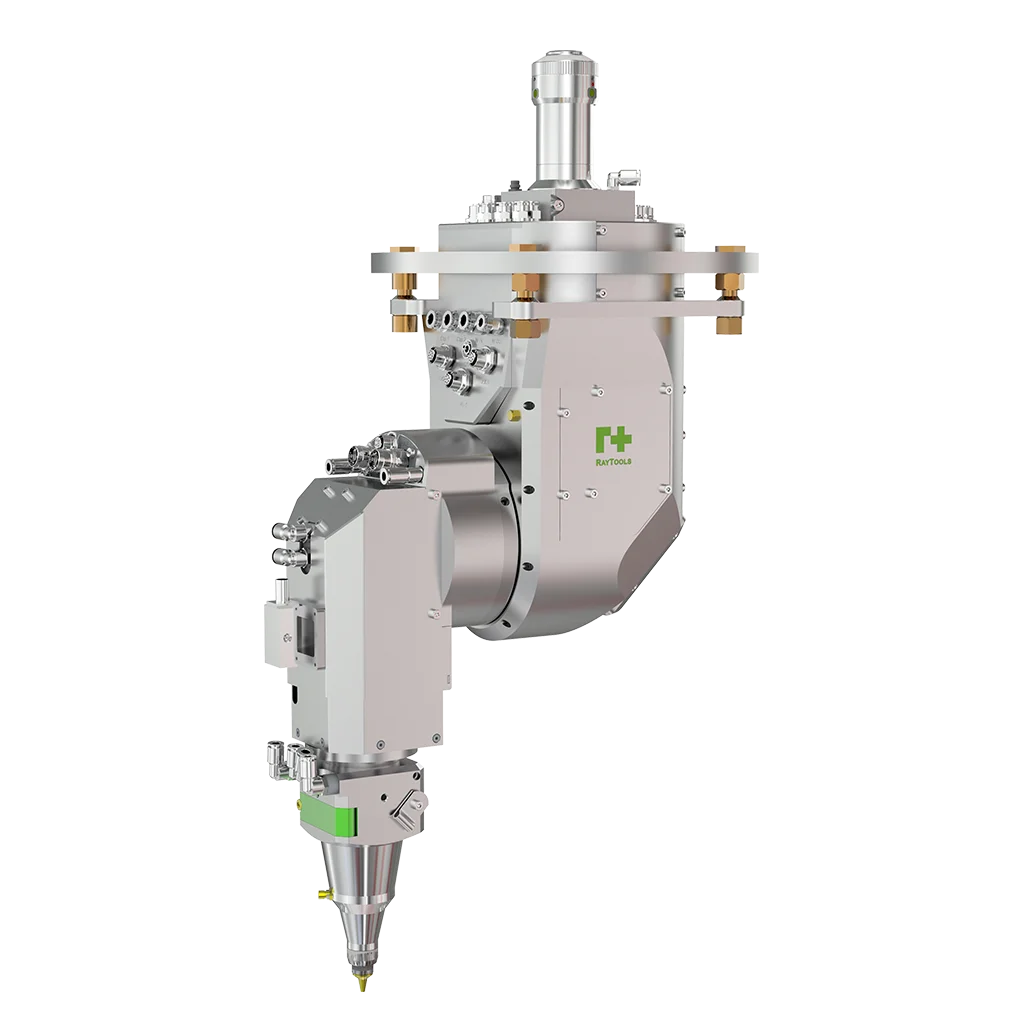
For manufacturers processing metal tubes and structural profiles, even small process variations can create substantial costs when multiplied across thousands of components. Excessive dross increases cleaning time, incomplete cuts generate scrap, and frequent nozzle or optical maintenance interrupts production. A systematic evaluation of the GF402 tube cutting head should therefore focus on measurable process performance, machine integration, and total operating cost rather than isolated component specifications.
RayTools operates in the laser intelligent manufacturing sector, providing solutions across cutting, drilling, welding, cladding, surface treatment, and other laser applications. In tube cutting, the same manufacturing principle applies: the cutting head, laser source, motion system, control software, and process parameters must function together to deliver repeatable results.
Why Cutting Efficiency Depends on the Entire System
A tube laser cutting machine performs several coordinated operations. The workpiece is loaded, positioned, clamped, rotated, and moved along the programmed path while the cutting head maintains the required relationship with the material surface. Depending on the part design, the process may include piercing, contour cutting, hole formation, bevel-related operations where supported, and repeated repositioning.
The effective production cycle is therefore longer than the time spent with the laser actively cutting. Loading delays, piercing time, motion transitions, acceleration and deceleration, scrap removal, and part unloading all influence output.
The GF402 tube cutting head contributes to the cutting stage, but it cannot independently eliminate delays caused by poor material handling or inefficient motion programming. Its value must be evaluated within the complete manufacturing process.
Consider a production line cutting square steel tubes for industrial frames. If most of the cycle time is spent repositioning the chuck, changing workpieces, or handling finished parts, increasing cutting speed may have only a limited effect on total output. If the dominant losses come from unstable penetration or repeated edge-quality defects, process optimization around the cutting head may provide a more direct improvement.
A useful baseline should include cycle time per part, first-pass yield, scrap rate, rework time, unplanned stoppages, and maintenance hours. Recording these values before a configuration change makes it possible to determine whether the GF402 tube cutting head delivers a measurable improvement under actual operating conditions.
Stabilizing Piercing and Continuous Cutting
Piercing is often one of the most sensitive stages of laser tube cutting. Before the programmed contour can be cut, the laser must establish a suitable opening through the material. Incorrect power settings, insufficient piercing time, unsuitable focus position, or unstable assist-gas conditions can cause excessive spatter, incomplete penetration, or damage to nearby surfaces.
These issues become more expensive in automated production because a single failed piercing operation may interrupt a complete cutting sequence. Spatter can also contaminate the nozzle or protective optical components, creating secondary performance problems.
When evaluating a GF402 tube cutting head, confirm the supported piercing process, optical configuration, nozzle options, and recommended operating conditions. The precise process window depends on the laser source, material grade, thickness, tube geometry, and machine control strategy.
For thicker carbon steel profiles, a controlled piercing sequence may be necessary to manage molten material and prevent excessive spatter. For thin-wall stainless steel tubes, excessive energy input can cause local overheating or unwanted deformation. The appropriate solution is not simply to maximize power but to establish a repeatable combination of power, focus position, gas pressure, and timing.
Production trials should examine both isolated piercing performance and the transition from piercing to continuous cutting. A stable transition helps reduce local defects at the start of the contour and supports consistent finished-part quality.
Optimizing Cutting Speed Without Sacrificing Quality
Increasing programmed speed does not always improve manufacturing productivity. When cutting speed exceeds the stable process window, the result may be incomplete penetration, rough edges, excessive dross, or inconsistent dimensions. Operators may then need to reduce speed, repeat the cut, or perform additional finishing operations.
The relationship between speed and quality varies with material and geometry. Thin-wall tubes can often be processed at higher speeds than thicker sections under otherwise comparable conditions, but the result also depends on laser output, focus characteristics, gas delivery, and the complexity of the cutting path.
Square and rectangular profiles create additional challenges at corners. Changes in motion direction can reduce instantaneous feed speed, while variations in local surface geometry may influence cutting conditions. Sharp corners, small holes, and closely spaced features can therefore require different settings from long straight cuts.
A practical approach is to develop process recipes for recurring combinations of material, wall thickness, tube geometry, and feature type. Each recipe should define the validated operating parameters and the acceptance criteria for finished parts.
For the GF402 tube cutting head, any claimed speed advantage should be supported by a controlled comparison using the same laser source, material batch, profile dimensions, and quality requirements. Comparing only maximum programmed speed can be misleading because it excludes rejected parts, rework, and process interruptions.
The more useful performance measure is the number of conforming parts produced per shift. This metric reflects both cutting capability and the stability required for repeatable manufacturing.
Assist-Gas Control and Consumable Management
Assist-gas performance has a direct influence on cutting stability. Gas pressure, flow consistency, nozzle geometry, and nozzle alignment affect the removal of molten material from the kerf. An unstable supply or damaged nozzle can reduce cut quality even when the laser source and cutting-head optics remain in good condition.
Nitrogen is commonly used where oxidation must be minimized, particularly for stainless steel applications requiring clean edges. Oxygen may be appropriate for selected carbon steel processes, while compressed air can be considered for applications in which the equipment, material, and surface-finish requirements permit it.
The correct selection depends on the intended process rather than a universal rule. Gas type and pressure should be validated together with the laser parameters, nozzle design, and material thickness.
Consumable management also affects equipment availability. Nozzles should be inspected for deformation, blockage, and damage after collisions or abnormal cutting events. Protective optics should be checked according to the manufacturer's maintenance procedure, with replacement triggered by condition or specified service criteria.
A GF402 tube cutting head evaluation should include the availability and cost of compatible consumables, the time required for inspection and replacement, and the accessibility of routine service points. These factors are especially important for production facilities running multiple shifts or automated lines with limited opportunities for manual intervention.
A documented maintenance schedule helps distinguish normal consumable wear from process instability. If nozzle damage or protective-window contamination occurs unusually often, the root cause may involve piercing parameters, gas quality, cutting debris, collision protection, or operating conditions rather than the consumable itself.
Reliability in Automated Tube Processing
Automated tube cutting systems must maintain process stability despite variations in tube dimensions, surface condition, and production frequency. Long workpieces may experience positioning deviations, while thinner profiles can deform during clamping or cutting. These issues affect the distance and orientation between the material and the cutting head.
Machine rigidity, chuck accuracy, workpiece support, and motion synchronization should therefore be evaluated alongside the cutting-head configuration. A high-quality optical assembly cannot compensate for unstable workpiece positioning or excessive mechanical vibration.
Before integrating a GF402 tube cutting head into an automated line, verify its mounting interface, supported laser and optical configuration, connection requirements, and operating limits. Particular attention should be paid to collision risks when cutting complex profiles, short parts, or tubes with narrow clearances.
Maintenance access should be considered during equipment layout. Protective-window inspection, nozzle replacement, connection checks, and routine cleaning should be possible without unnecessarily dismantling surrounding equipment. In high-utilization factories, easier servicing can reduce the time between fault detection and production restart.
Reliability testing should extend beyond a short demonstration. A production trial should include repeated cutting cycles, representative material changes, normal machine acceleration and deceleration, and the features most likely to produce defects. Monitoring performance over a meaningful production interval can reveal problems that may not appear during a brief sample cut.
Measuring Total Cost of Ownership
The financial value of a cutting-head configuration depends on more than its initial purchase price. The total cost of ownership includes acquisition, integration, consumables, maintenance labor, energy and gas consumption, rejected parts, and downtime attributable to the cutting process.
For example, a configuration that reduces dross may lower secondary finishing costs. More stable piercing can reduce interrupted cycles, while easier maintenance may shorten routine service periods. These benefits should be quantified using actual factory data rather than assumed from product descriptions.
A simple cost-per-part assessment can be expressed as:
Cost per conforming part = Total production cost ÷ Number of conforming parts produced
Total production cost should cover the same operating period used to count conforming parts. Depending on the purpose of the evaluation, it may include machine depreciation, labor, consumables, assist gas, maintenance, scrap, and rework. Keeping the calculation consistent makes comparisons between configurations more meaningful.
When comparing the GF402 tube cutting head with an alternative, the test conditions must remain equivalent. Use the same workpiece specification, laser source where feasible, required edge quality, production volume, and acceptance criteria. Record actual output and maintenance requirements rather than relying solely on nominal speed or advertised capability.
The resulting data provides a stronger basis for estimating whether a configuration can improve throughput, reduce waste, or support a more predictable production schedule.
Technical Verification Before Deployment
Before finalizing an installation, the GF402 tube cutting head should be checked against the requirements of the intended machine and application. The key items include supported laser power, optical specifications, focusing arrangements, mounting dimensions, nozzle interfaces, cooling requirements where applicable, and approved operating conditions.
Material trials should cover the most common production profiles as well as difficult cases, such as maximum wall thickness, small-diameter tubes, sharp corners, and closely spaced holes. Acceptance criteria should be established in advance for dimensional accuracy, edge condition, dross, piercing reliability, and cycle time.
The manufacturer's current technical documentation should be used to verify all model-specific values. The designation GF402 alone is not sufficient evidence of a particular focal length, maximum laser power, cutting thickness, or compatibility with a given machine.
Where an existing line is being upgraded, the integration assessment should also account for electrical and control interfaces, mechanical alignment, safety interlocks, and any required software or parameter changes. This reduces the risk of discovering compatibility issues after the component has been installed.
Conclusion
The GF402 tube cutting head should be assessed through measurable improvements in cutting stability, finished-part quality, maintenance efficiency, and overall production output. Piercing reliability, cutting speed, assist-gas performance, optical maintenance, and machine integration all influence the result.
For manufacturers seeking to improve automated tube processing, the most effective strategy is to establish a production baseline, validate the cutting-head configuration under representative conditions, and compare the total cost per conforming part. By combining verified technical specifications with real production data, factories can make a more informed decision about whether the GF402 tube cutting head meets their application requirements and supports long-term manufacturing reliability.
www.raytools.com
RayTools


+ There are no comments
Add yours